Translation

Showing posts with label AUTO CAD. Show all posts

9.8.10

Model Space & Layout (Paper) Space

The Autocad screen tells us we are in model space in the two following locations:


The left hand model tab has two default tabs next to it named 'Layout1' and 'Layout2'. These are shortcuts to the two default paper space views 'Layout1' and 'Layout2'.
By double clicking the right hand model button shown above, this will take us to the default paper space view Layout1.
What is Paper space?
Many beginners to Autocad get confused about paper space, so we'll try and make it as painless as possible! The concept is in fact very simple!
By now you should be familiar with model space, and what it is. To summarise; model space is the main drawing area in Autocad.
Paper space is an area used in Autocad to plot (print) the drawing created in model space. Paper space is a lot more powerful than simply letting us plot the entire model space drawing, we can set up views called Viewports within the paper space area to separately show different areas of the model space drawing.
Paper space is actually a blank sheet, the separate viewports showing different views of the model are what creates a printable drawing.
The screen shot above shows a paper space layout created named 'A4 Layout view - Paper space 1'. Notice how earlier where the screen showed us that we were in model space, it now says paper to indicate paper space.
A rectangle measuring 275x200mm was drawn in paper space, so that it would fit nicely on an A4 sized sheet of paper.
All Autocad commands that are used in model space can be used in paper space, however everything in paper space should be drawn at 1:1 (full size) in millimetres if the drawing is to be printed to scale.
The rectangle drawn is simply a frame which will provide a border to the drawing, when plotted.
Notice how each of the three views of the guitar head are bordered by a black rectangle, these are in fact separate viewports - each looking at the same 3D model in model space, but looking from different angles.
Think of paper space as the piece of paper you wish to print on to, with holes cut away where you want different parts of the model space drawing to be shown. The model can be moved closer or further away from the hole, and also panned around. The view of the model in one view port is totally independent from the view in another, and zooming into one viewport will not affect the view of other viewports within the paper space.
Practice - Using Paper space Viewports
Download the Autocad drawing file lesson10.dwg, which is the above drawing of a Gibson Les Paul guitar head. The A4 paper space layout has already been created for you.
Lesson10.dwg (Autocad 2000 File)
Lesson10 r14.dwg (Autocad R14 File)

1) The drawing will open in model space, with the guitar head centred within the screen.
2) Click the tab next to the 'model' tab which says 'A4 Layout View - Paper space 1'. This will take us out of model space and into paper space.
The A4 sized rectangle frame with a title block is shown. This was drawn directly onto paper space, just like as if we were drawing in model space. Zoom out a little, notice the white box - this is the edge of the A4 sheet when plotted. In paper space, provided your plotter is set to the correct paper size setting, what you see is what you get. Generally, what is shown on paper space is what will be plotted.
Currently, there are no views of the model. We must add a viewport to be able to 'see through' the paper space and into model space.
4) Under the 'view' drop down menu, go to viewports -> 1 viewport. Drawing a viewport is exactly the same as drawing a rectangle, simply two opposite corners have to be specified.
Draw a viewport roughly in the centre of the A4 frame, as shown below.
Notice how the model is zoomed extents to the viewport. We have now created a viewport within paper space, ready for plotting.
Working with Viewports
Once a viewport is created, it itself can be modified, and so can its view. To activate a viewport, double click within the viewport window. The cross hair movement is now restricted to the viewport window. The bottom status bar will now indicate that we have entered model space, although we are still in paper space. Effectively, we are in model space, but working in model space through paper space. To exit out of the viewport, simply double click out of the viewport (or double click the status bar at the bottom of the screen to toggle between model/paper space).

Once a viewport is created, its contents can be changed by activating it, and zooming/panning throughout the drawing to change the view. We can even work on the model through paper space, as all the usual commands are still active
.A viewport can be moved around in paper space using the move command, however a viewport cannot be rotated. To change the size of a viewport, select it while in paper space, and change its size by dragging the blue grips at each corner of the viewport.
To hide the rectangular frame of a viewport, simply create a new layer, turn the layer off then add the viewport to the layer. The viewport frame will then become invisible, although the viewport still functions. Of course, when you want to move/resize the viewport, don't forget to turn the layer back on!

Plotting to Scale
To be able to plot an Autocad drawing to scale, we need to set the zoom factor within the viewport. Setting the zoom factor enables us to fix the scale of the viewport when plotting from paper space at 1:1 (NOT scale to fit!).

To set a viewport to a scale is a simple procedure, we simply need to recognise if within model space we decided to draw in metres or millimetres i.e does one Autocad unit represent 1mm or 1m?

The zoom factor of a drawing is known as its XP value, and the xp value is determined as below (if one Autocad unit represents 1m):
XP Value (m) = 1000/scale req'd
Example:
Viewport scale required = 1:200
XP Value = 1000/200 = 5
Zoom Factor = 5xp
If the model is drawn that 1 Autocad unit represents 1mm, then the above formula applies, but the zoom factor must then be divided by 1000.
XP Value (mm) = ( 1000/scale req'd ) / 1000

Example:
Viewport scale required = 1:200
XP Value = ( 1000/200 ) / 1000 = 5/1000 = 0.005
Zoom Factor = 0.005xp
The table below summarises the XP zoom scale factors for the common scales:


Don't forget that within paper space, we can have as many viewports as we like (although the more viewports active, the more PC memory is used which can affect your system's performance).
Plotting
Now that we know how to set up a paper space view with scaled viewports, we simply have to plot it to a printer for a true scale, paper copy of the drawing.
Printing from Autocad is simple, we just have to ensure that a few settings are correct.

To open the plot menu, click the plot icon
on the standard toolbar, or select 'plot' from the file drop down menu. The plot dialogue box will appear:

First of all, click the 'plot device' tab to select the printer you wish to plot to:

The printer can be selected from the drop down list, the properties of the printer can also be selected to change print quality e.t.c.

Plot style is where we can choose the colour of the plot, based on the on-screen colours. For example, every red line within Autocad can be set to print red, or could be set to print out black. This setting can be left as none for now.

Full preview is where we can preview the print, but only after we have chosen our plot setup in 'plot settings'.

Partial preview provides a simplified preview of the drawing, useful for previewing large drawings which would take a while to regenerate all the viewports for the preview.

Back to the 'Plot settings' tab:


Paper size - select the paper size of the print out (This will usually be the size of the frame drawn in paper space. In the case of the lesson10.dwg tutorial file, this should be set to A4.

Drawing Orientation - Simply landscape or portrait. For this example set it to landscape, to match the paper space layout.
Plot scale - This is where the entire paper space scale is set. Remember earlier when we said that everything in paper space should be drawing in millimetres at 1:1 full size? For the print to plot to scale, plot scale MUST be set to 1:1.
If a quick 'not to scale' plot is required of a drawing (or part of a drawing - see plot area below) the plot scale can be set to 'scaled to fit' to fill the paper with the selected print area.
Plot Area - We must select which part of the drawing we wish to plot. In this case, we wish to plot the entire A4 frame in paper space:

Layout - this will plot the current layout.
Extents - Similar to zoom extents. The extents of the paper space area will be plotted.
Display - The current screen display will be plotted.
Window - This is the most useful tool to select the plot area. Similar to zoom window, plot window allows us to select the exact area to be plotted by selecting a rectangle around the required area.
Select the Window radio button, then click the 'window< ' box to select the window area. Choose the top left then bottom right corners of the blue A4 frame in paper space.
Plot offset - This enables us to select the position of the plot on the paper. For best results, select 'centre the plot' to plot the drawing central to the paper sheet.
Plot Options - these settings can be left as they are.

Now that we have defined our plot settings, go back to the 'plot device' tab and select 'full preview' to see a preview of the print job. It should be similar to the screen shot below:

Finally, to exit the preview, right click and select exit. This takes us back to the plot dialogue box. Go back to the 'plot settings' tab and select the 'plot' button to send the drawing to the printer.


Zoom Commands

1) Load up the file, the drawing is of a steel plate with 6 mounting screws.

To see all of the available zoom commands, the zoom toolbar needs to be visible. Load in the zoom toolbar (For those who can't remember: Go to the 'view' drop down menu, then select toolbars. Check the 'zoom' box then choose close. Move the toolbar to a convenient location)
AutoCAD's zoom command toolbar:


Commands (From Left to Right):

Zoom Window : Select a window over the location to zoom into. AutoCAD will zoom in close to the object including everything within the selection box.

Zoom Dynamic : Enables the user to set the size of a standard zoom window type box, then use this box to select zoom in views of the drawing with this box with clicks of the mouse button. (Not as powerful as zoom window in my opinion)
Zoom Scale : Enables the user to zoom into the drawing to a known scale (referred to as an 'XP value'). This type of zoom is not required until you are ready to plot the drawing. Don't worry, you're not expected to understand the use of this command yet! It will be covered in the paperspace/layout view tutorial.
Zoom Centre : Specify a centre point, then a radius and AutoCAD will centre this view to fit your screen.
Zoom In : Pretty simple, zooms into the drawing slightly by each click! Quick 'n' simple!
Zoom Out : Same as above, but zoom out by each click.
Zoom All : Zooms to the extents of the drawing limits. Don't worry about this just yet.
Zoom Extent : This is a very useful command. One press will zoom to the extent of the entire drawing enabling a very quick overview of the project and an easy starting point to zoom into a more precise area of the drawing with one of the above tools.

2) You should have the lesson3.dwg file open in AutoCAD. If not then open it up now. Time to try some zoom commands out.
3) Press the zoom window button. AutoCAD asks for the first corner of the box you are about to draw. This corner can be any corner of the zoom box we will specify. Choose an area just to the top left of the left side middle screw (see below). AutoCAD now asks for the opposite corner, select to the bottom right of the screw ensuring the screw is clearly inside the zoom box.
You should now have a clear view of the screw.


4) Now try the zoom in and zoom out buttons. Notice how they knock the zoom in and out by a set amount each time, just comfortable enough to get a wider/closer view where required.
5) Now press the zoom extents button. This zooms back to see the entire drawing centred in the screen.

Have a play with the commands , viewing different areas of the drawing until you feel comfortable manipulating the zoom to suit the view you require.

Zoom Realtime / Pan Command
By now you should be comfortable with operating the zoom commands. Now we'll try the easiest and perhaps most used zoom command available, zoom realtime. This command is located on the toolbar named 'standard toolbar'.
1) Select the zoom realtime button .
2) This command will zoom in and out of the drawing dependant on how far you move your mouse. Left click and hold the left mouse button down. AutoCAD will zoom in further into the drawing the further you move you mouse up (away from you). Try pulling the mouse down with the left button still held down, AutoCAD will zoom out. Once mastered, zoom realtime will become your preferred method of quickly zooming into a drawing.

3) Now we'll introduce a command which quickly enables you to change the view of the screen without altering the zoom. You probably noticed that while zooming with any of the above commands, you sometimes wanted to view either further left, right, up or down on the drawing. This wasn't possible with the zoom commands without zooming out and then zooming in again showing the area you require. The pan tool enables us to control exactly which area we are viewing.

4) Select the pan button
5) While holding the left mouse button, pull the mouse to the left, right, up or down. Notice how the pan tool reflects these mouse movements on screen so we can move around the screen effortlessly.

Top Tip! - Combining the zoom real time and pan commands is by far the quickest way to navigate a drawing. While either command is open, try right clicking the mouse in the drawing area to bring up a small menu where the most common and useful zoom commands can be quickly selected : pan, zoom (realtime), zoom window and zoom extents. Get used to right clicking to change zoom commands to easily navigate any AutoCAD drawing.

Just one last note, but an often misunderstood concept for new AutoCAD users. Zooming DOES NOT affect the drawing scale in any way. The dimensions of the drawing remain the same! We are simply manipulating the view.
For example; A car viewed from a Plane traveling at 10,000ft appears quite small, when viewed from 25,000ft it appears tiny! The size of the car however has not altered, we are simply viewing it from further away!


29.7.10

Adding Sunlight

    Introduction

    Once you start working with solid models and rendering them, you will want to add lighting effects to your model. One of the most common requirements is to add sunlight to your drawing. AutoCAD has some very powerful and useful features for accurately creating sunlight effects.
    As you may have realised by now, you don't need lights in a scene in order to render a model. Figure number 1 on the left shows the effect of rendering without lights. As you can see, the results are rather uninspiring and there are no shadows. AutoCAD calculates the lighting in a scene where there are no lights by determining the the angle of incidence between the object faces and the line of sight. Faces that are perpendicular or near perpendicular to the line of sight are displayed brighter and faces further from the perpendicular are shown darker. The effect is similar to what you would see if the light source was placed at the camera position; perpendicular faces would reflect more light and faces further from the perpendicular would reflect less light. In figure 1, you can see that the vertical faces of the hedge, facing the viewer are bright, whereas the ground plane is quite dark. Although this effect enables you to clearly see your model, it is far from realistic.
    In order to add some sunlight to our scene, we will need to add a light that simulates the sun; AutoCAD calls this type of light a "Distant Light". This is much easier than it sounds and AutoCAD has some very user-friendly tools to help.
    As you can see from figures 2, 3 and 4, not only can you simulate sunlight but you can control the time of day, the day of the year and the geographic location. Also, because the renderer can create accurate shadows based upon your parameters, you could even use these techniques to create a shadow analysis.
    The three sunlight images on the left show the light and shadow effects on a garden at different times of the day on the 25th June in London. This is all possible without needing to know the first thing about solar geometry!
    This tutorial will take you, step-by-step through the process of creating sunlight, modifying it and making the necessary shadow and render settings.

    Adding sunlight and rendering a drawing is essentially a 5 step process. If you are familiar with AutoCAD, you may be able to create sunlight by following the Fast Track steps below. If you have never worked with lights before or have never used the renderer, I suggest you follow the full tutorial. Start by downloading the Sample Data or go straight to Getting Started.Overview & Fast Track

    Fast Track

    1. Create a Distant Light using the Light command, ViewRenderLight… from the pull-down menu. Set the light type to "Distant Light" and click the New… button.
    2. Name the light and set Shadow Type to "Raytraced" in the New Distant Light dialogue box. Give the new light a name. Click the checkbox to turn shadows on and then click the Shadow Options… button. Click the checkbox to turn "Ray Traced Shadows" on.
    3. Set the Time using the Sun Angle Calculator. Click the Sun Angle Calculator… button in the New Distant Light dialogue box.
    4. Set the Location from the Sun Angle Calculator dialogue box. Click the Geographic Location… button in the Sun Angle Calculator dialogue box.
    5. Render the Scene using the Render command, ViewRenderRender… from the pull-down menu. Set the "Rendering Type" to Photo Raytrace and click the checkbox to turn "Shadows" on.

    You can use any 3D drawing to follow this tutorial providing that you have drawn a ground plane on which the shadows can be projected. Alternatively, you can download the file shown in the images above. Click on the icon below to download the AutoCAD drawing file Garden.dwg. There are two download options, you can either download the drawing file or you can download the smaller compressed file. The compressed Zip file can be uncompressed with a utility such as WinZip.Download Sample Data

    Download Garden.dwg (367KB) Garden.dwg (367KB) - AutoCAD 2000 Drawing File
    Download Garden.zip (73KB) Garden.zip (73KB) - AutoCAD File Zipped
    Save the file to the folder where you keep your AutoCAD drawing files. If you downloaded the zipped version, you will need to unzip it before continuing.

    Open the Garden.dwg file. You may notice that it is a little slow to open. This is because the garden is constructed from solid objects and AutoCAD has to load some extra bits of the program to deal with them. The opening view is an aerial perspective. This was created using the DVIEW command but you could also use 3D Orbit. The view has been saved so that you can return to it at any time using the Named Views command, Named Views from the Standard toolbar orViewNamed Views…. Highlight the view name, "Sun View", click the "Set Current" button and then click OK.Getting Started

    In addition to the saved view, the garden drawing also has the various render settings already saved for you. However, if you are not familiar with rendering, it would be useful to have a quick go now so that you know what to expect later in the tutorial.
    After opening the Garden.dwg, select ViewRenderRender… from the pull-down menu or click Render on the render toolbar to display the Render dialogue box. Since all of the settings are already made, simply click the OK button. After a few moments, the rendered image will appear in your viewport and your screen should look something like the image above. Notice that the render background has been set to white. This just makes the rendered objects easier to see. Notice also that some of the objects have materials assigned.
    Note that rendered views are not interactive, they are just still images, like photographs. You cannot pan, zoom or pick objects in a rendered view as you can in shaded views. Therefore, you must return to your previous viewing mode before continuing with any drawing work. To do this, you must regenerate the view, select ViewRegen from the pull-down menu.
    The rendered image that you see is shown with the default lighting as described above and illustrated in figure 1. We have not yet added any lights, so this is the next thing to do.

    ToolbarLight
    Pull-downViewRenderLight…
    KeyboardLIGHT
    Adding a Light

    The first step toward simulating sunlight is to create a new "Distant Light".
    AutoCAD can create 3 different types of light, namely, Point Light, Spotlight and Distant Light. It is important to understand how each of these light types affects the final rendered image. A point light radiates light in all directions from a single point. A real-world example of this type of light is the bulb of a ceiling pendant light. A spotlight creates a conical light that is also directional. This is similar to a real-world spotlight. Distant lights differ from both point lights and spotlights in that their light rays are not radial, they are parallel.
    Lights Dialogue Box
    Why are distant lights used to simulate sunlight? Well, although light rays from the Sun are radial, we are so far away from the Sun that the angle between light rays is very small by the time they reach the Earth. To all intents and purposes, they are parallel and since light rays from distant lights are parallel, they most closely resemble sunlight.
    So, to create a new distant light, select ViewRenderLight… from the pull-down menu. When the Lights dialogue box appears, select "Distant Light" from the drop-down list and then click the New… button. This will take you to the New Distant Light dialogue box.

    The second step to simulating sunlight is to name the light and to set the shadow options.Configuring a Distant Light

    Click in the "Light Name" edit box and type the name of your new distant light. For the sake of simplicity, it might be sensible to call the light "SUN". However, you can call it anything you like providing that it is eight characters or less and doesn't include any of the normal illegal characters such as spaces, asterisks, slashes and dots. If the light name you choose is not liked by AutoCAD, you will see a small error message in the lower left-hand corner of the dialogue box saying "Invalid name".
    New Distant Light Dialogue Box
    Setting shadow options for a light involves turning shadows on and then specifying the shadow type. When you create any light, you can decide whether it will cast shadows or not. In some cases it is desirable that lights do not cast shadows. This ability to control shadow casting means that you could build a scene with a number of lights, some of which cast shadows and some of which don't. To turn shadows on, click in the "Shadow On" checkbox (shadows are turned off by default).
    Now you can set the shadow type. Click the Shadow Options… button to display the Shadow Options dialogue box.

    The AutoCAD renderer can create three different types of shadows. The default shadow type is "Shadow Map" and the alternatives are "Volumetric" and "Ray Traced". You can see from the illustrations below that the shadow map and ray traced shadow types give quite different results. For most objects, the difference between Volumetric and Ray Traced shadows is very small. See All about Shadows for a full description of these shadow types. The type of shadow you use is entirely up to you but in general, ray traced shadows tend to give a better result.Setting Shadow Options

     Shadow Map ShadowsRay Traced Shadows
    Shadow Options Dialogue Box
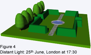
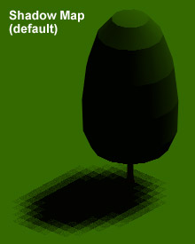
The Shadow Options dialogue box is used to specify which shadow type is used when you render the scene. The default shadow type is the shadow map.
    Click the "Shadow Volumes/Ray Traced Shadows" check box to change the shadow type. Your dialogue box should now look like the one on the right. Click the OK button to return to the New Distant Light dialogue box.

    The third step in simulating sunlight is to set the date and time using the Sun Angle Calculator. From the New Distant Light dialogue box, click the Sun Angle Calculator… button to display the Sun Angle Calculator dialogue box.Using the Sun Angle Calculator

    Sun Angle Calculator Dialogue Box
    In order to set the date and time, you must specify the date, the time, the time zone and decide whether you want daylight savings or not.
    Starting at the top of the left-hand column in the dialogue box, click in the "Date" edit box and type the date. Note that dates are in the American format (mm/dd). Next, click in the "Clock Time" edit box and enter the time. Note that this is in 24 hour format or military time. If you wish, you can use the adjacent slider bars to set the date and time but it is very difficult to control accurately and is therefore not recommended.
    Using the drop-down list, select the required time zone. For example, if your site is in the UK, select the "GMT/WET" option. Finally, you need to decide whether you would like daylight savings to be calculated. This option will automatically convert GMT (Greenwich Mean Time) to BST (British Summer Time). Most likely you will want to have this option turned on, so click the "Daylight Savings" checkbox.
    You will notice that AutoCAD allows you to specify the latitude and longitude of your site. These values must be known in order for AutoCAD to accurately calculate the angle of the Sun. In most cases you won't know these values but fortunately, AutoCAD can help us to locate our site Geographically. Click the Geographic Location… button.

    The fourth step in simulating sunlight is to specify the geographic location of your site. The Geographic Location dialogue box enables you to do this in a number of ways.Setting the Geographic Location

    Geographic Location Dialogue Box
    The first thing to do is to specify which continent your site is in. Use the drop-down list, centre top of the dialogue box, to select a continent. Once you have done this, you have a number of options. You can simply select the name of a city from the list on the left. You can also select a city by checking the "Nearest Big City" option and picking a point on the map. If your site is not near a big city, you can deselect this option and simply pick any point on the map. Obviously it is very difficult to accurately pick a location from such a small map but you should be able to get close enough to generate realistic shadows.
    You have now made all the settings that are needed to simulate sunlight. Click the OK button to return to the Sun Angle Calculator dialogue box. Click the OK button again to return to the New Distant Light dialogue box, click OK a third time to return to the Lights dialogue box and finally, click OK one more time to complete the specification for your distant light.
    This might be a good time to save your drawing if you haven't already done so.

    ToolbarRender
    Pull-downViewRenderRender…
    KeyboardRENDER
    Rendering the Scene

    The fifth and final step to simulating sunlight is to render a view of your drawing in order to show the effects of light and shadow.
    Render Dialogue Box
    Start the Render command by selecting ViewRenderRender… from the pull-down menu. The Render dialogue box will appear. First, make sure that the Rendering Type option is set to "Photo Raytrace". Next, make sure that "Shadows" is checked in the Rendering Options section of the dialogue box. Shadows will not be generated if this option is not checked, even if shadows are turned on for your lights.
    If you are not using the Garden sample drawing, you should also check that the Destination is set to "Viewport". You may also like to set the render background colour to white.
    When you are sure that all settings have been made correctly (your dialogue box should look similar to the one illustrated above), click the Render button. AutoCAD will take a few seconds to render the scene (times will vary depending upon the complexity of the scene and the speed of your computer).

    Once you have created your first sunlight render, you may want to change the time of day or date of the year in order to demonstrate the changing effect of sunlight on your site. You can modify your distant light settings at any time. To do so, select ViewRenderLight… from the pull-down menu to go to the Lights dialogue box. Select your light from the list on the left of the dialogue box and click the Modify… button. This will take you to the Modify Distant Light dialogue box.Modifying Sun Light

    Modify Distant Light Dialogue Box
    From here you can modify any of the settings you made when you first configured the light. When your changes have been made, render the scene again and you will see the results of your modification. You could use this technique to create images of your site at hourly intervals during a single day or at the same time of day at different times of the year. This will give a good idea how sunlight will affect your site at different times.

    Hot Tips

    Distant Light Icon
    • You may notice that when you create a light for the first time in a drawing, you not only gain a light but you also gain a small icon representing the light and a special new layer. Distant lights are displayed using the icon shown on the right and the name of the light is also shown. Do not move or erase distant light icons. Erasing the icon will delete the light. The new layer created for the light icon is called "ASHADE" and it is a special AutoCAD layer. Do not use this layer for anything else.ASHADE layerHowever, if you would like to hide your light icons, turn this layer off or freeze it.
    • To save your rendered images to file, set the Destination in the Render dialogue box to "File" and then use the More Options… button to configure file output.
    • Remember that shadows are only visible if they are cast against some solid object. For example, if you want to see shadows cast on the ground, you will need to draw a ground plane.
    • Working with shadow mapped shadows can be tricky and AutoCAD can sometimes throw up unexpected results. Use raytraced shadows to avoid confusion. See the All about Shadows tutorial for more details.